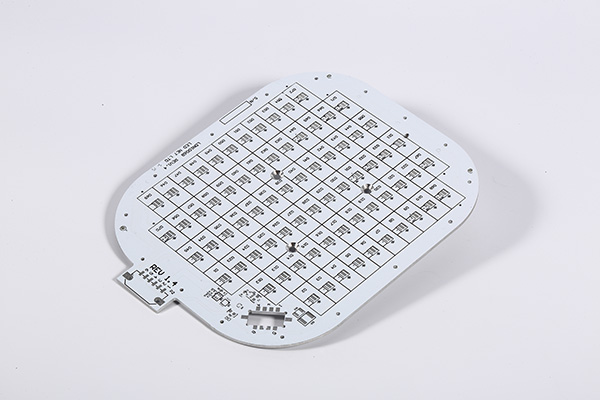
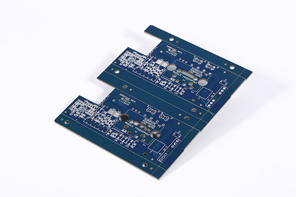
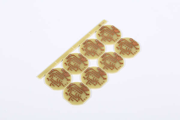
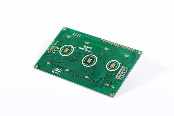
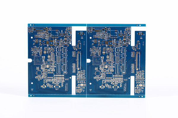
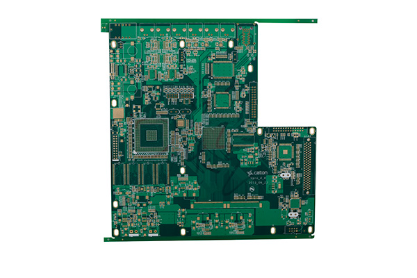
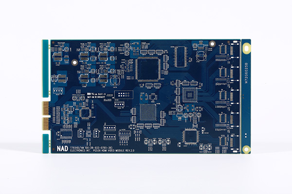
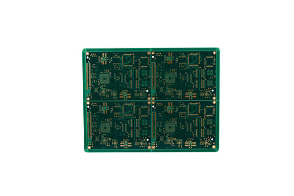
One Stop PCB & PCBA Solution Provider

Printed circuit board artwork generation was initially a fully manual process done on clear mylar sheets at a scale of usually 2 or 4 times the desired size. The schematic diagram was first converted into a layout of components pin pads, then traces were routed to provide the required interconnections. Pre-printed non-reproducing mylar grids assisted in layout, and rub-on dry transfers of common arrangements of circuit elements (pads, contact fingers, integrated circuit profiles, and so on) helped standardize the layout. Traces between devices were made with self-adhesive tape. The finished layout "artwork" was then photographically reproduced on the resist layers of the blank coated copper-clad boards.
In the design of the PCB artwork, a power plane is the counterpart to the ground plane and behaves as an ACsignal ground, while providing DC voltage for powering circuits mounted on the PCB. In electronic design automation (EDA) design tools, power planes (and ground planes) are usually drawn automatically as a negative layer, with clearances or connections to the plane created automatically.